Fractional distillation is the separation of a mixture into its component components, or fractions. Chemical compounds are separated by heating them to a temperature at which one or more fractions of the mixture will vaporize. It uses distillation to fractionate. Typically the component elements have boiling factors that differ by lower than 25 °C from one another underneath a strain of 1 ambiance. If the difference in boiling factors is higher than 25 °C, a simple distillation is usually used.
1 Laboratory setup 1.1 Apparatus
1.2 Dialogue
2.1 Design of industrial distillation columns
Laboratory setup[edit]
Fractional distillation in a laboratory makes use of common laboratory glassware and apparatuses, typically including a Bunsen burner, a spherical-bottomed flask and a condenser, in addition to the single-goal fractionating column.
Apparatus[edit]
– heat source, resembling a sizzling plate with a bath, and ideally with a magnetic stirrer.
– distilling flask, usually a round-backside flask
– receiving flask, often also a round-backside flask
fractionating column
– distillation head
thermometer and adapter if needed
condenser, such as a Liebig condenser or Allihn condenser
– vacuum adapter (not used in picture to the right)
boiling chips, also known as anti-bumping granules
– Standard laboratory glassware with ground glass joints, e.g. quickfit apparatus.
Discussion[edit]
As an example consider the distillation of a mixture of water and ethanol. Ethanol boils at 78.4 °C while water boils at one hundred °C. So, by heating the mixture, the most volatile component (ethanol) will concentrate to a higher degree in the vapor leaving the liquid. Some mixtures kind azeotropes, the place the mixture boils at a lower temperature than either part. In this instance, a mixture of 96% ethanol and 4% water boils at 78.2 °C; the mixture is extra volatile than pure ethanol. Because of this, ethanol can’t be fully purified by direct fractional distillation of ethanol-water mixtures.
The apparatus is assembled as in the diagram. (The diagram represents a batch apparatus as opposed to a steady apparatus.) The mixture is put into the round bottomed flask along with a number of anti-bumping granules (or a Teflon coated magnetic stirrer bar if utilizing magnetic stirring), and the fractionating column is fitted into the highest. The fractional distillation column is arrange with the heat source at the underside on the nonetheless pot. As the gap from the stillpot will increase, a temperature gradient is formed within the column; it’s coolest at the top and hottest at the underside. Because the mixed vapor ascends the temperature gradient, some of the vapor condenses and revaporizes alongside the temperature gradient. Each time the vapor condenses and vaporizes, the composition of the extra risky element in the vapor increases. This distills the vapor along the size of the column, and eventually the vapor is composed solely of the extra volatile part (or an azeotrope). The vapor condenses on the glass platforms, often called trays, inside the column, and runs again down into the liquid under, refluxing distillate. The efficiency when it comes to the amount of heating and time required to get fractionation may be improved by insulating the outside of the column in an insulator corresponding to wool, aluminium foil or ideally a vacuum jacket. The hottest tray is at the bottom and the coolest is at the top. At regular state situations, the vapor and liquid on each tray are at equilibrium. Essentially the most volatile element of the mixture exits as a gas at the highest of the column. The vapor at the highest of the column then passes into the condenser, which cools it down till it liquefies. The separation is more pure with the addition of extra trays (to a practical limitation of heat, movement, etc.) Initially, the condensate will be near the azeotropic composition, however when much of the ethanol has been drawn off, the condensate becomes steadily richer in water.[quotation needed] The process continues until all of the ethanol boils out of the mixture. This point will be acknowledged by the sharp rise in temperature proven on the thermometer.
The above explanation reflects the theoretical way fractionation works. Regular laboratory fractionation columns can be easy glass tubes (typically vacuum-jacketed, and sometimes internally silvered) filled with a packing, typically small glass helices of four to 7 mm diameter. Such a column will be calibrated by the distillation of a identified mixture system to quantify the column in terms of variety of theoretical trays. To enhance fractionation the apparatus is about as much as return condensate to the column by means of some form of reflux splitter (reflux wire, gago, Magnetic swinging bucket, and so on.) – a typical careful fractionation would employ a reflux ratio of around four:1 (4 elements returned condensate to 1 part condensate take off).
In laboratory distillation, several kinds of condensers are generally found. The Liebig condenser is solely a straight tube inside a water jacket, and is the best (and relatively least costly) type of condenser. The Graham condenser is a spiral tube inside a water jacket, and the Allihn condenser has a sequence of giant and small constrictions on the inside tube, every increasing the floor area upon which the vapor constituents could condense.
Alternate set-ups could use a multi-outlet distillation receiver flask (referred to as a “cow” or “pig”) to connect three or four receiving flasks to the condenser. By turning the cow or pig, the distillates might be channeled into any chosen receiver. As a result of the receiver does not need to be eliminated and changed through the distillation process, any such apparatus is helpful when distilling below an inert atmosphere for air-delicate chemicals or at lowered strain. A Perkin triangle is an alternative apparatus often used in these conditions because it allows isolation of the receiver from the rest of the system, however does require eradicating and reattaching a single receiver for every fraction.
Vacuum distillation systems function at reduced stress, thereby decreasing the boiling points of the materials. Anti-bumping granules, however, grow to be ineffective at decreased pressures.
Industrial distillation[edit]
Fractional distillation is the most typical type of separation know-how utilized in petroleum refineries, petrochemical and chemical plants, natural gas processing and cryogenic air separation plants.[2][three] Usually, the distillation is operated at a continuous steady state. New feed is all the time being added to the distillation column and products are at all times being eliminated. Unless the process is disturbed resulting from adjustments in feed, heat, ambient temperature, or condensing, the quantity of feed being added and the quantity of product being eliminated are usually equal. This is named continuous, steady-state fractional distillation.
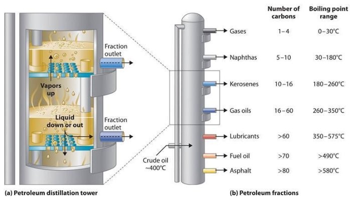
Industrial distillation is usually carried out in massive, vertical cylindrical columns known as “distillation or fractionation towers” or “distillation columns” with diameters starting from about 65 centimeters to 6 meters and heights starting from about 6 meters to 60 meters or more. The distillation towers have liquid retailers at intervals up the column which permit for the withdrawal of different fractions or products having completely different boiling factors or boiling ranges. By increasing the temperature of the product contained in the columns, the completely different hydrocarbons are separated. The “lightest” products (these with the lowest boiling level) exit from the top of the columns and the “heaviest” merchandise (these with the very best boiling point) exit from the underside of the column.
For example, fractional distillation is utilized in oil refineries to separate crude oil into useful substances (or fractions) having totally different hydrocarbons of various boiling factors. The crude oil fractions with larger boiling points:
– have more carbon atoms
– have larger molecular weights
– are less branched chain alkanes
– are darker in color
– are more viscous
– are more difficult to ignite and to burn
Large-scale industrial towers use reflux to realize a extra full separation of products. Reflux refers back to the portion of the condensed overhead liquid product from a distillation or fractionation tower that is returned to the upper a part of the tower as proven in the schematic diagram of a typical, giant-scale industrial distillation tower. Contained in the tower, the reflux liquid flowing downwards provides the cooling needed to condense the vapors flowing upwards, thereby increasing the effectiveness of the distillation tower. The more reflux is provided for a given number of theoretical plates, the better the tower’s separation of decrease boiling supplies from greater boiling materials. Alternatively, the more reflux provided for a given desired separation, the fewer theoretical plates are required.
Fractional distillation can be utilized in air separation, producing liquid oxygen, liquid nitrogen, and highly concentrated argon. Distillation of chlorosilanes also enable the manufacturing of high-purity silicon for use as a semiconductor.
In industrial makes use of, generally a packing materials is used within the column instead of trays, especially when low stress drops throughout the column are required, as when operating under vacuum. This packing material can either be random dumped packing (1-three” wide) corresponding to Raschig rings or structured sheet steel. Typical manufacturers are Koch, Sulzer and other firms. Liquids tend to wet the surface of the packing and the vapors move throughout this wetted floor, the place mass transfer takes place. Not like conventional tray distillation during which each tray represents a separate point of vapor liquid equilibrium the vapor liquid equilibrium curve in a packed column is steady. Nonetheless, when modeling packed columns it is helpful to compute plenty of “theoretical plates” to indicate the separation effectivity of the packed column with respect to extra conventional trays. Differently formed packings have totally different surface areas and void space between packings. Both of these components have an effect on packing efficiency.
Design of industrial distillation columns[edit]
Design and operation of a distillation column depends upon the feed and desired products. Given a simple, binary component feed, analytical methods such because the McCabe-Thiele technique[3][four][5] or the Fenske equation[three] can be utilized. For a multi-component feed, simulation models are used both for design and operation.
Moreover, the efficiencies of the vapor-liquid contact devices (known as plates or trays) utilized in distillation columns are typically decrease than that of a theoretical a hundred% efficient equilibrium stage. Therefore, a distillation column wants more plates than the number of theoretical vapor-liquid equilibrium phases.
Reflux refers to the portion of the condensed overhead product that’s returned to the tower. The reflux flowing downwards supplies the cooling required for condensing the vapours flowing upwards. The reflux ratio, which is the ratio of the (internal) reflux to the overhead product, is conversely associated to the theoretical number of stages required for environment friendly separation of the distillation products. Fractional distillation towers or columns are designed to achieve the required separation efficiently. The design of fractionation columns is generally made in two steps; a course of design, adopted by a mechanical design. The aim of the method design is to calculate the number of required theoretical stages and stream flows together with the reflux ratio, heat reflux and other heat duties. The aim of the mechanical design, then again, is to pick out the tower internals, column diameter and top. In most cases, the mechanical design of fractionation towers is just not simple. For the environment friendly selection of tower internals and the correct calculation of column top and diameter, many elements should be taken into consideration. Some of the elements involved in design calculations include feed load measurement and properties and the kind of distillation column used.
The 2 main types of distillation columns used are tray and packing columns. Packing columns are usually used for smaller towers and masses which might be corrosive or temperature delicate or for vacuum service where pressure drop is important. Tray columns, on the other hand, are used for larger columns with high liquid loads. They first appeared on the scene within the 1820s. In most oil refinery operations, tray columns are mainly used for the separation of petroleum fractions at different phases of oil refining.
Within the oil refining trade, the design and operation of fractionation towers is still largely accomplished on an empirical basis. The calculations involved in the design of petroleum fractionation columns require in the usual apply the use of numerable charts, tables and advanced empirical equations. Lately, nevertheless, a considerable amount of labor has been done to develop environment friendly and dependable pc-aided design procedures for fractional distillation.[6]
Azeotropic distillation
Batch distillation
Extractive distillation
Freeze distillation
Steam distillation
 ^ Laurence M. Harwood; Christopher J. Moody (thirteen June 1989). Experimental organic chemistry: Principles and Observe (Illustrated ed.). pp. 145-147. ISBN 978-zero-632-02017-1.
^ Kister, Henry Z. (1992). Distillation Design (1st ed.). McGraw-Hill. ISBN zero-07-034909-6.
^ a b c Perry, Robert H.; Inexperienced, Don W. (1984). Perry’s Chemical Engineers’ Handbook (6th ed.). McGraw-Hill. ISBN zero-07-049479-7.
^ Beychok, Milton (Could 1951). “Algebraic Answer of McCabe-Thiele Diagram”. Chemical Engineering Progress.
^ Seader, J. D.; Henley, Ernest J. (1998). Separation Course of Ideas. New York: Wiley. ISBN zero-471-58626-9.
^ Ibrahim, Hassan Al-Haj (2014). “Chapter 5”. In Bennett, Kelly. Matlab: Purposes for the practical Engineer. Sciyo. pp. 139-171. ISBN 978-953-51-1719-3.
In case you adored this post as well as you would want to receive more details with regards to Petroleum Machinery manufacture kindly visit our web-site.