Steady distillation, a form of distillation, is an ongoing separation in which a mixture is continuously (with out interruption) fed into the method and separated fractions are eliminated continuously as output streams. Distillation is the separation or partial separation of a liquid feed mixture into components or fractions by selective boiling (or evaporation) and condensation. The method produces not less than two output fractions. These fractions embody no less than one unstable distillate fraction, which has boiled and been individually captured as a vapor condensed to a liquid, and virtually always a bottoms (or residuum) fraction, which is the least risky residue that has not been individually captured as a condensed vapor.
 Another to continuous distillation is batch distillation, where the mixture is added to the unit at the beginning of the distillation, distillate fractions are taken out sequentially in time (one after another) throughout the distillation, and the remaining bottoms fraction is removed at the top. Because each of the distillate fractions are taken out at different times, only one distillate exit point (location) is required for a batch distillation and the distillate can just be switched to a different receiver, a fraction-accumulating container. Batch distillation is commonly used when smaller portions are distilled. In a continuous distillation, each of the fraction streams is taken concurrently throughout operation; due to this fact, a separate exit level is needed for each fraction. In follow when there are a number of distillate fractions, the distillate exit points are situated at totally different heights on a fractionating column. The bottoms fraction will be taken from the bottom of the distillation column or unit, but is commonly taken from a reboiler connected to the underside of the column.
Each fraction could include one or more elements (forms of chemical compounds). When distilling crude oil or the same feedstock, every fraction incorporates many components of related volatility and different properties. Although it is feasible to run a small-scale or laboratory steady distillation, most often steady distillation is used in a large-scale industrial course of.
Contents
1 Industrial software
2 Principle
3 Design and operation three.1 Column feed
three.2 Enhancing separation 3.2.1 Reflux
3.2.2 Plates or trays
3.2.Three Packing
4.1 Continuous distillation of crude oil
Industrial application[edit]
Distillation is without doubt one of the unit operations of chemical engineering.[1][2] Continuous distillation is used widely within the chemical process industries where giant portions of liquids should be distilled.[3][4][5] Such industries are the natural gas processing, petrochemical production, coal tar processing, liquor production, liquified air separation, hydrocarbon solvents production and related industries, however it finds its widest application in petroleum refineries. In such refineries, the crude oil feedstock is a very advanced multicomponent mixture that should be separated and yields of pure chemical compounds should not expected, solely groups of compounds within a relatively small range of boiling points, which are called fractions. These fractions are the origin of the term fractional distillation or fractionation. It is commonly not worthwhile separating the elements in these fractions any further based mostly on product requirements and economics.
Industrial distillation is typically carried out in large, vertical cylindrical columns (as proven in pictures 1 and 2) generally known as “distillation towers” or “distillation columns” with diameters ranging from about 65 centimeters to 11 meters and heights ranging from about 6 meters to 60 meters or more.
Precept[edit]
The principle for steady distillation is identical as for regular distillation: when a liquid mixture is heated so that it boils, the composition of the vapor above the liquid differs from the liquid composition. If this vapor is then separated and condensed right into a liquid, it becomes richer in the lower boiling point part(s) of the unique mixture.
That is what happens in a continuous distillation column. A mixture is heated up, and routed into the distillation column. On entering the column, the feed starts flowing down however a part of it, the component(s) with decrease boiling point(s), vaporizes and rises. Nevertheless, as it rises, it cools and whereas part of it continues up as vapor, some of it (enriched within the less risky part) begins to descend again.
Image three depicts a easy continuous fractional distillation tower for separating a feed stream into two fractions, an overhead distillate product and a bottoms product. The “lightest” products (those with the bottom boiling point or highest volatility) exit from the top of the columns and the “heaviest” merchandise (the bottoms, those with the highest boiling point) exit from the underside of the column. The overhead stream may be cooled and condensed utilizing a water-cooled or air-cooled condenser. The bottoms reboiler may be a steam-heated or sizzling oil-heated heat exchanger, or even a fuel or oil-fired furnace.
In a continuous distillation, the system is saved in a gradual state or approximate regular state. Regular state implies that quantities related to the process do not change as time passes during operation. Such constant portions embrace feed input fee, output stream charges, heating and cooling rates, reflux ratio, and temperatures, pressures, and compositions at each point (location). Unless the method is disturbed resulting from modifications in feed, heating, ambient temperature, or condensing, steady state is generally maintained. This can be the main attraction of steady distillation, apart from the minimum quantity of (easily instrumentable) surveillance; if the feed fee and feed composition are kept constant, product charge and quality are also fixed. Even when a variation in circumstances occurs, modern course of control strategies are generally in a position to steadily return the continuous course of to a different steady state once more.
Since a steady distillation unit is fed always with a feed mixture and not crammed all at once like a batch distillation, a steady distillation unit does not need a sizable distillation pot, vessel, or reservoir for a batch fill. Instead, the mixture may be fed instantly into the column, where the actual separation happens. The height of the feed level along the column can differ on the situation and is designed so as to offer optimum outcomes. See McCabe-Thiele method.
A continuous distillation is commonly a fractional distillation and is usually a vacuum distillation or a steam distillation.
Design and operation[edit]
Design and operation of a distillation column is dependent upon the feed and desired merchandise. Given a simple, binary component feed, analytical methods such as the McCabe-Thiele technique[5][6][7] or the Fenske equation[5] can be used to assist within the design. For a multi-element feed, computerized simulation fashions are used both for design and subsequently in operation of the column as properly. Modeling can also be used to optimize already erected columns for the distillation of mixtures other than those the distillation gear was originally designed for.
When a steady distillation column is in operation, it must be carefully monitored for changes in feed composition, operating temperature and product composition. Many of those tasks are performed using advanced computer control equipment.
Column feed[edit]
The column might be fed in different ways. If the feed is from a supply at a pressure greater than the distillation column pressure, it is simply piped into the column. In any other case, the feed is pumped or compressed into the column. The feed may be a superheated vapor, a saturated vapor, a partially vaporized liquid-vapor mixture, a saturated liquid (i.e., liquid at its boiling point on the column’s strain), or a sub-cooled liquid. If the feed is a liquid at a a lot increased pressure than the column stress and flows by way of a stress let-down valve just ahead of the column, it would instantly increase and undergo a partial flash vaporization resulting in a liquid-vapor mixture as it enters the distillation column.
Bettering separation[edit]
Though small dimension items, largely manufactured from glass, might be used in laboratories, industrial models are massive, vertical, steel vessels (see pictures 1 and a couple of) often known as “distillation towers” or “distillation columns”. To enhance the separation, the tower is generally provided inside with horizontal plates or trays as proven in picture 5, or the column is packed with a packing material. To provide the heat required for the vaporization involved in distillation and in addition to compensate for heat loss, heat is most frequently added to the underside of the column by a reboiler, and the purity of the top product may be improved by recycling a number of the externally condensed prime product liquid as reflux. Depending on their objective, distillation columns could have liquid shops at intervals up the length of the column as proven in image four.
Reflux[edit]
Massive-scale industrial fractionation towers use reflux to attain extra environment friendly separation of products.[Three][5] Reflux refers back to the portion of the condensed overhead liquid product from a distillation tower that’s returned to the upper a part of the tower as proven in photographs 3 and 4. Contained in the tower, the downflowing reflux liquid offers cooling and partial condensation of the upflowing vapors, thereby rising the efficacy of the distillation tower. The extra reflux that’s supplied, the higher is the tower’s separation of the lower boiling from the higher boiling parts of the feed. A balance of heating with a reboiler at the bottom of a column and cooling by condensed reflux at the highest of the column maintains a temperature gradient (or gradual temperature difference) along the top of the column to offer good circumstances for fractionating the feed mixture. Reflux flows on the middle of the tower are known as pumparounds.
Changing the reflux (together with modifications in feed and product withdrawal) can be used to improve the separation properties of a steady distillation column whereas in operation (in contrast to including plates or trays, or altering the packing, which would, at a minimal, require quite significant downtime).
Plates or trays[edit]
Distillation towers (similar to in pictures three and 4) use varied vapor and liquid contacting strategies to provide the required variety of equilibrium phases. Such gadgets are generally referred to as “plates” or “trays”.[Eight] Every of these plates or trays is at a distinct temperature and strain. The stage on the tower bottom has the very best stress and temperature. Progressing upwards in the tower, the stress and temperature decreases for each succeeding stage. The vapor-liquid equilibrium for every feed component in the tower reacts in its unique way to the different strain and temperature situations at each of the stages. Meaning that every element establishes a distinct focus in the vapor and liquid phases at each of the stages, and this outcomes in the separation of the parts. Some instance trays are depicted in image 5. A more detailed, expanded image of two trays may be seen within the theoretical plate article. The reboiler often acts as an extra equilibrium stage.
If each physical tray or plate had been one hundred% environment friendly, then the variety of bodily trays needed for a given separation would equal the number of equilibrium stages or theoretical plates. Nevertheless, that may be very seldom the case. Therefore, a distillation column wants more plates than the required variety of theoretical vapor-liquid equilibrium levels.
Packing[edit]
Another approach of bettering the separation in a distillation column is to use a packing materials as a substitute of trays. These offer the advantage of a decrease strain drop throughout the column (when compared to plates or trays), helpful when operating under vacuum. If a distillation tower makes use of packing instead of trays, the number of crucial theoretical equilibrium levels is first decided after which the packing height equivalent to a theoretical equilibrium stage, identified because the peak equal to a theoretical plate (HETP), can also be determined. The whole packing top required is the variety of theoretical phases multiplied by the HETP.
This packing materials can either be random dumped packing comparable to Raschig rings or structured sheet steel. Liquids tend to wet the surface of the packing and the vapors go throughout this wetted surface, the place mass switch takes place. In contrast to typical tray distillation in which every tray represents a separate point of vapor-liquid equilibrium, the vapor-liquid equilibrium curve in a packed column is steady. Nevertheless, when modeling packed columns it is useful to compute plenty of theoretical plates to indicate the separation efficiency of the packed column with respect to more conventional trays. Otherwise formed packings have different floor areas and void house between packings. Both of those elements affect packing efficiency.
Another factor along with the packing form and floor space that affects the performance of random or structured packing is liquid and vapor distribution coming into the packed mattress. The variety of theoretical levels required to make a given separation is calculated utilizing a specific vapor to liquid ratio. If the liquid and vapor are not evenly distributed across the superficial tower area as it enters the packed mattress, the liquid to vapor ratio won’t be correct within the packed mattress and the required separation won’t be achieved. The packing will seem to not be working properly. The height equivalent to a theoretical plate (HETP) will be better than anticipated. The problem is just not the packing itself however the mal-distribution of the fluids getting into the packed mattress. Liquid mal-distribution is more regularly the issue than vapor. The design of the liquid distributors used to introduce the feed and reflux to a packed bed is critical to creating the packing perform at most efficiency. Methods of evaluating the effectiveness of a liquid distributor will be present in references.[9][10]
Overhead system arrangements[edit]
Images four and 5 assume an overhead stream that is completely condensed right into a liquid product using water or air-cooling. However, in lots of circumstances, the tower overhead is not simply condensed totally and the reflux drum should include a vent fuel outlet stream. In but other instances, the overhead stream may additionally contain water vapor as a result of either the feed stream contains some water or some steam is injected into the distillation tower (which is the case in the crude oil distillation towers in oil refineries). In those circumstances, if the distillate product is insoluble in water, the reflux drum could include a condensed liquid distillate phase, a condensed water section and a non-condensible fuel part, which makes it vital that the reflux drum also have a water outlet stream.
Examples[edit]
Steady distillation of crude oil[edit]
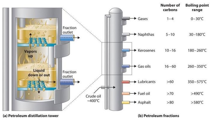
Petroleum crude oils include a whole lot of various hydrocarbon compounds: paraffins, naphthenes and aromatics as well as natural sulfur compounds, natural nitrogen compounds and some oxygen containing hydrocarbons similar to phenols. Although crude oils generally don’t comprise olefins, they’re formed in many of the processes utilized in a petroleum refinery.[Eleven]
The crude oil fractionator doesn’t produce merchandise having a single boiling level; quite, it produces fractions having boiling ranges.[11][12] For example, the crude oil fractionator produces an overhead fraction known as “naphtha” which becomes a gasoline element after it is additional processed by means of a catalytic hydrodesulfurizer to take away sulfur and a catalytic reformer to reform its hydrocarbon molecules into extra complicated molecules with a better octane rating value.
The naphtha lower, as that fraction known as, incorporates many various hydrocarbon compounds. Due to this fact, it has an preliminary boiling level of about 35 °C and a last boiling level of about 200 °C. Every reduce produced within the fractionating columns has a unique boiling range. At some distance under the overhead, the following lower is withdrawn from the facet of the column and it is often the jet gas cut, also referred to as a kerosene cut. The boiling range of that reduce is from an preliminary boiling level of about a hundred and fifty °C to a remaining boiling point of about 270 °C, and it also incorporates many alternative hydrocarbons. The following reduce additional down the tower is the diesel oil minimize with a boiling range from about 180 °C to about 315 °C. The boiling ranges between any lower and the following lower overlap as a result of the distillation separations are usually not completely sharp. After these come the heavy gas oil cuts and at last the bottoms product, with very huge boiling ranges. All these cuts are processed further in subsequent refining processes.
See also[edit]
Azeotropic distillation
Extractive distillation
Fractional distillation
Fractionating column
Steam distillation
References[edit]
^ Editors: Jacqueline I. Kroschwitz and Arza Seidel (2004). Kirk-Othmer Encyclopedia of Chemical Know-how (fifth ed.). Hoboken, New Jersey: Wiley-Interscience. ISBN 0-471-48810-0. CS1 maint: Extra textual content: authors checklist (link)
^ McCabe, W., Smith, J. and Harriott, P. (2004). Unit Operations of Chemical Engineering (seventh ed.). McGraw Hill. ISBN zero-07-284823-5. CS1 maint: Multiple names: authors listing (hyperlink)
^ a b Kister, Henry Z. (1992). Distillation Design (1st ed.). McGraw-Hill. ISBN 0-07-034909-6.
^ King, C.J. (1980). Separation Processes (2nd ed.). McGraw Hill. Petroleum Equipment Supplier ISBN 0-07-034612-7.
^ a b c d Perry, Robert H.; Inexperienced, Don W. (1984). Perry’s Chemical Engineers’ Handbook (sixth ed.). McGraw-Hill. ISBN zero-07-049479-7.
^ Beychok, Milton (Might 1951). “Algebraic Solution of McCabe-Thiele Diagram”. Chemical Engineering Progress.
^ Seader, J. D.; Henley, Ernest J. (1998). Separation Process Principles. New York: Wiley. ISBN 0-471-58626-9.
^ Photographs of bubble cap and different tray types (Website of Raschig Gmbh)
^ Random Packing, Vapor and Liquid Distribution: Liquid and gasoline distribution in industrial packed towers, Moore, F., Rukovena, F., Chemical Plants & Processing, Version Europe, August 1987, p. Eleven-15
^ Structured Packing, Liquid Distribution: A new methodology to assess liquid distributor high quality, Spiegel, L., Chemical Engineering and Processing 45 (2006), p. 1011-1017
^ a b Gary, J.H.; Handwerk, G.E. (1984). Petroleum Refining Technology and Economics (2nd ed.). Marcel Dekker, Inc. ISBN 0-8247-7150-8.
^ Nelson, W.L. (1958). Petroleum Refinery Engineering (4th ed.). McGraw Hill. LCCN 57010913.
External hyperlinks[edit]
Distillation Principle by Ivar J. Halvorsen and Sigurd Skogestad, Norwegian College of Science and Technology, Norway
Distillation by the Distillation Group, USA
Distillation Lecture Notes by Prof. Randall M.